
Joint © 2026 by Sahib Singh is licensed under CC BY-NC-SA 4.0![]()
![]()
![]()
![]()
INTRODUCTION
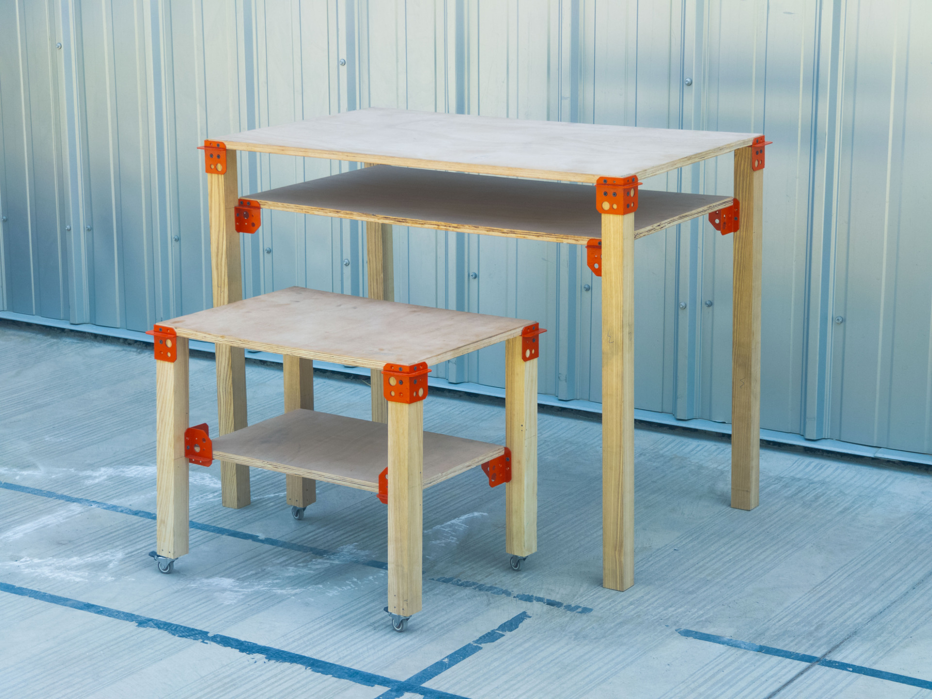
Joint is a three-axis connector designed to democratize structural assembly. Engineered to receive both linear and planar members, it exists as an incomplete entity, a mediator that is only realized when it comes into contact with standard materials like timber, plywood, or pipe. Moving away from restrictive, predefined flat-pack structures, this system establishes an open condition through which multiple outcomes can emerge. From rigid shelving frameworks and robust plywood tables to raw, brutalist lighting fixtures, the junction does not dictate what is to be made. It simply facilitates the making, offering an adaptable, hackable ecosystem where a single standardized element can solve a vast array of spatial and functional needs.
CONCEPT
Contemporary spatial design often falls into two categories: expensive pre-assembled objects or rigid flat-pack systems that dictate a singular, unchangeable final form. This project proposes a third path: an open-source hardware ecosystem that provides the structural logic but leaves the final outcome entirely to the user.
HARDWARE
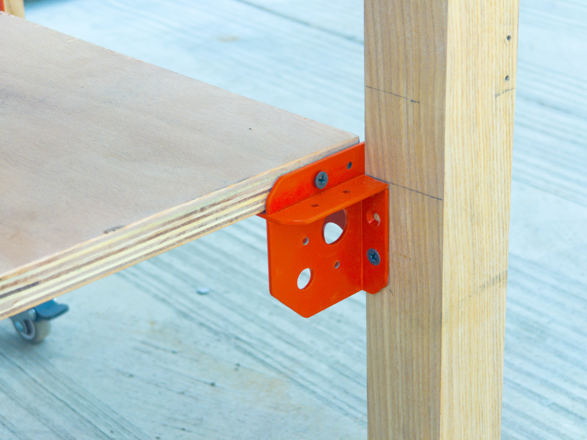
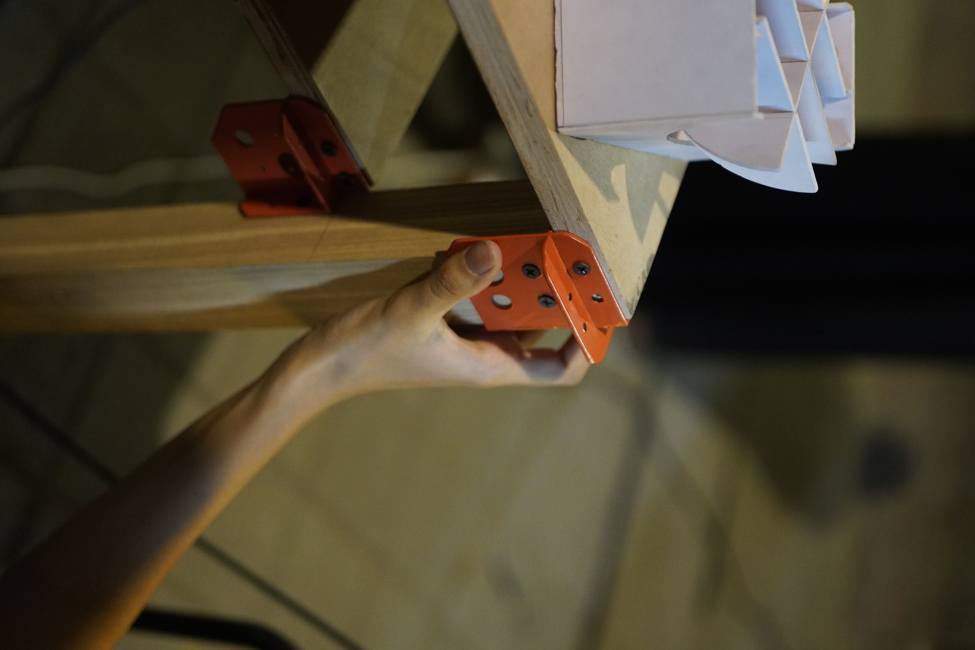
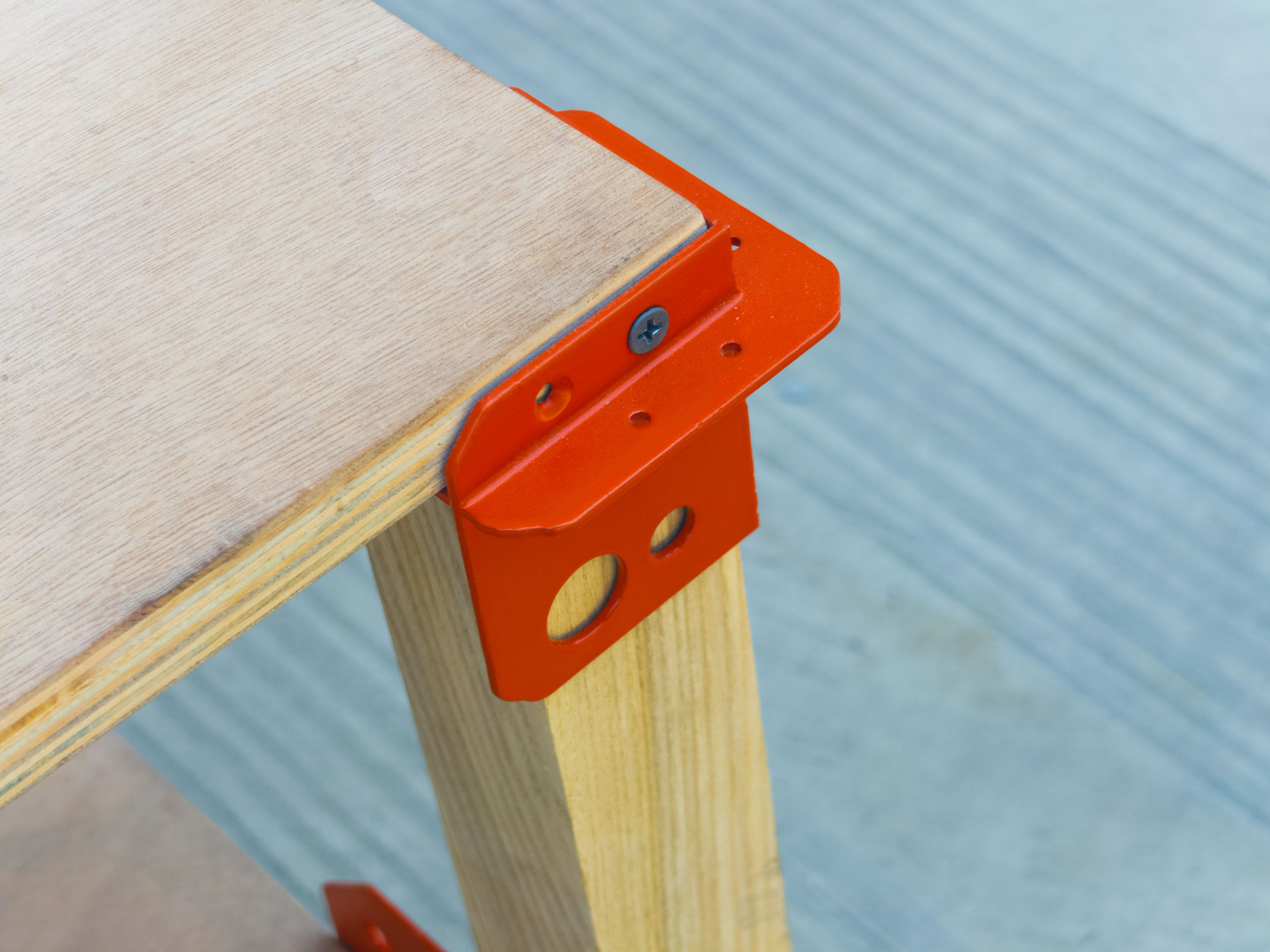
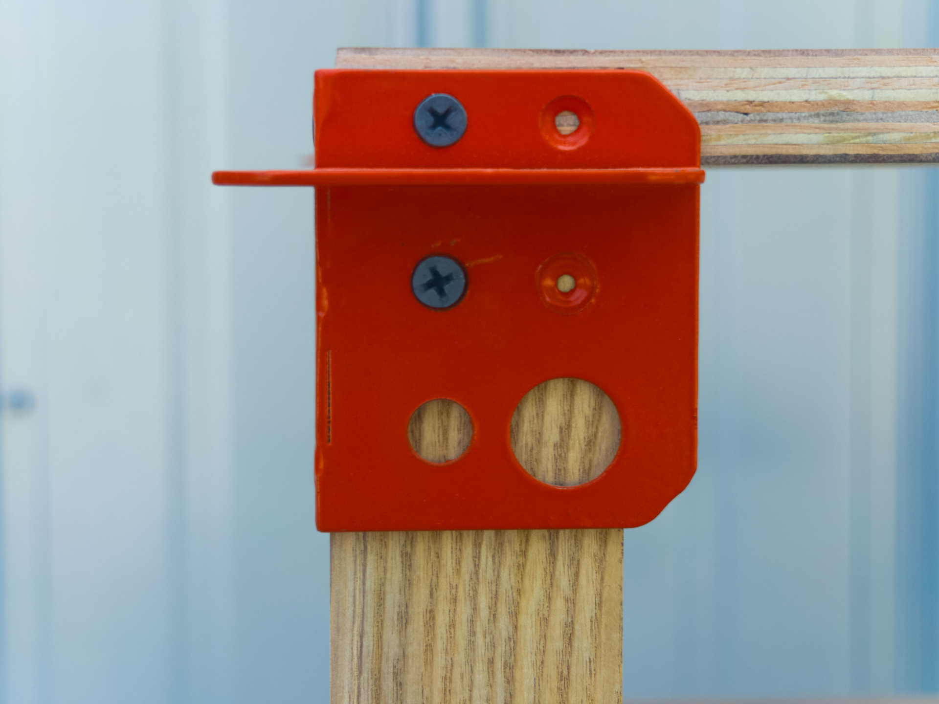
At the core of this system is a universal three-axis junction. Manufactured from planar metal pieces that are later interlocked, the bracket features a specific geometric hole pattern designed to seamlessly grip both linear members (such as square timber, round dowels, or PVC pipe) and planar members (such as plywood sheets). It relies entirely on standard, accessible fasteners, emphasizing a democratized, highly accessible approach to physical assembly.
SYSTEM CAPABILITIES
By functioning as a pure point of convergence, the junction enables systems that extend in multiple directions simultaneously. It does not prescribe a singular configuration; rather, it establishes a condition that supports: Spanning Structures, Vertical Assemblies, Enclosed Volumes.
THE PROTOTYPES
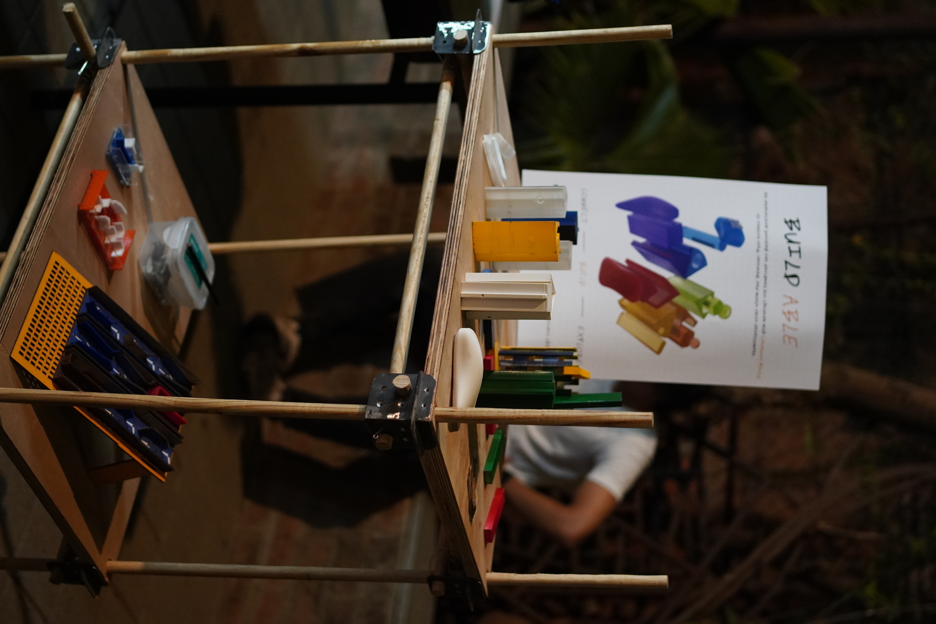
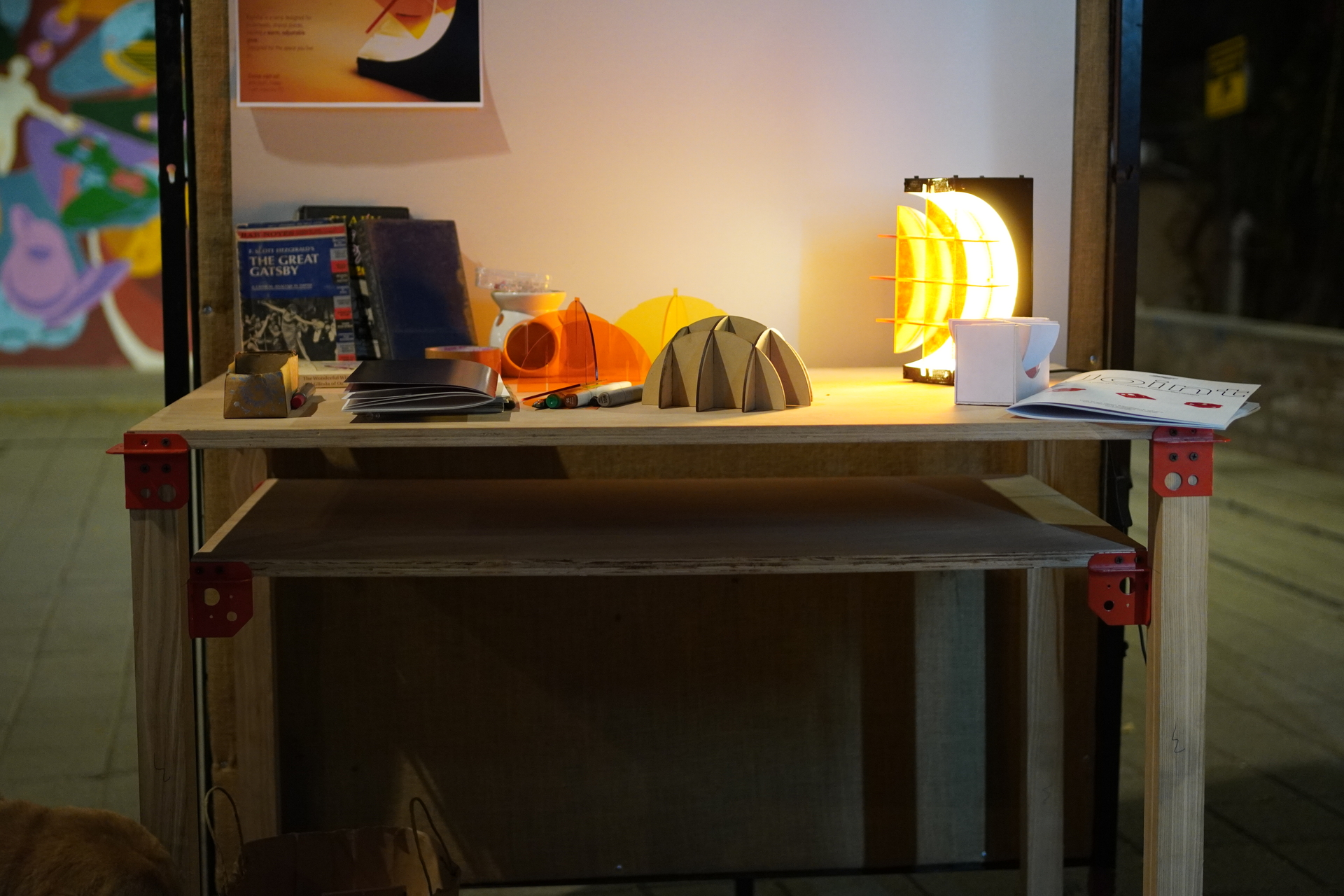
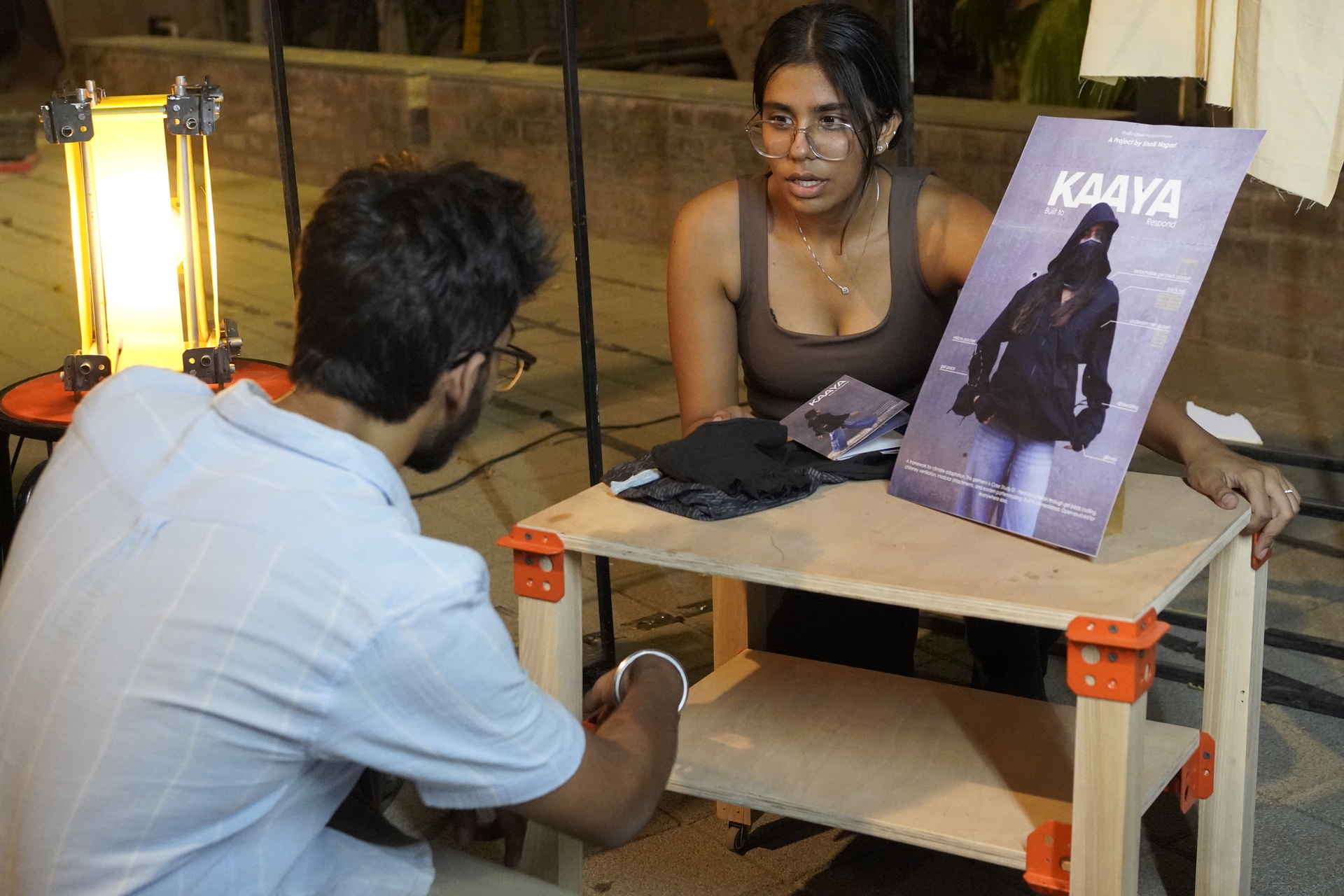
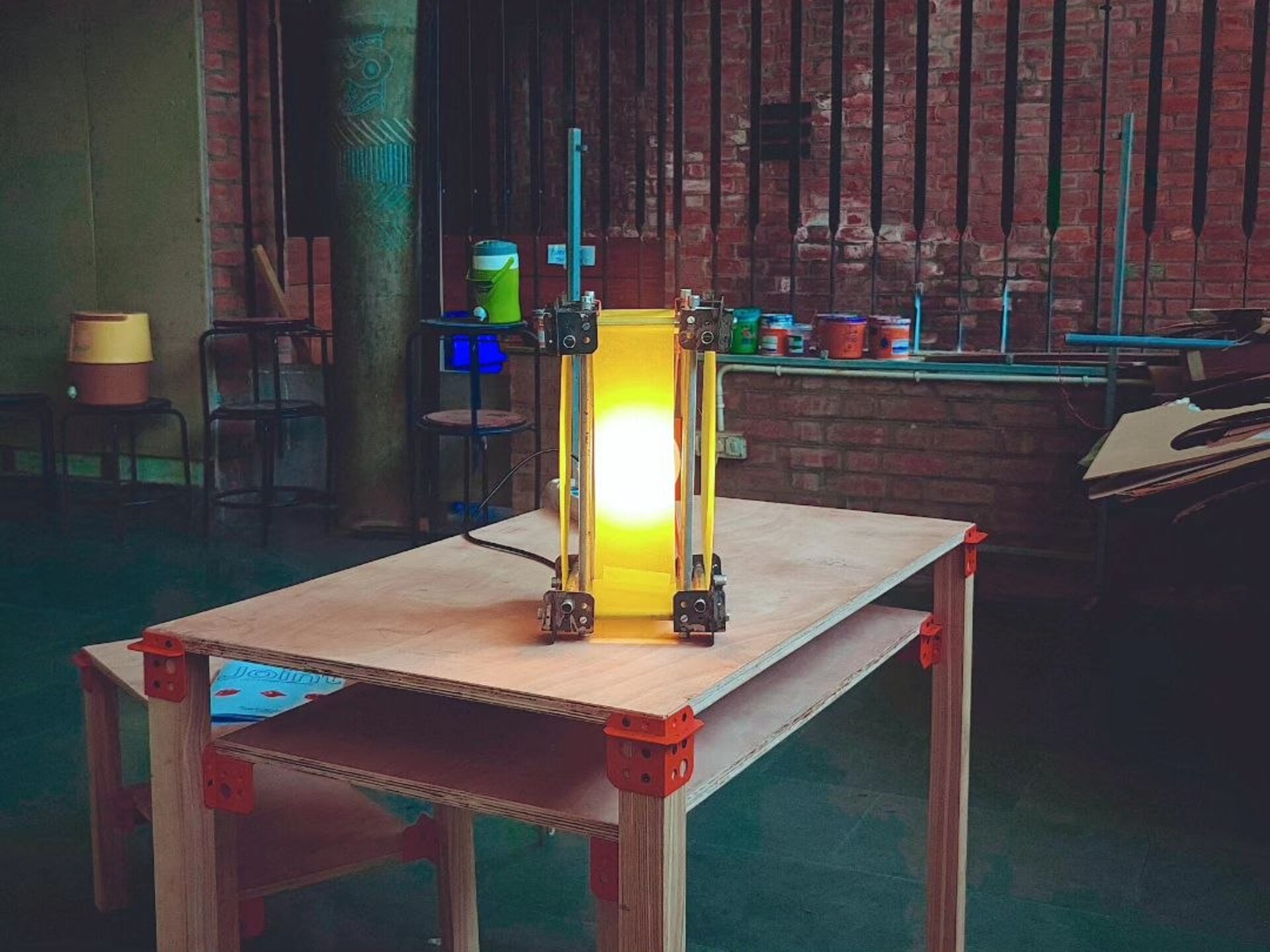
To test the limits of the system, several distinct instances were prototyped. The high-fidelity models, a robust table and stool, demonstrate the joint’s ability to grip raw timber and plywood, creating flush, stable, and highly functional utilitarian structures. The bright powder-coated hardware creates a stark, utilitarian contrast against the natural wood grain. To prove the system’s true flexibility, the hardware was then applied to other materials. An adaptable shelving framework was built utilizing standard round dowels, and a low-fidelity utility shelf was constructed using wooden dowels paired with plywood. Finally, an unpainted, raw-metal iteration of the joint was clamped onto found, untreated pipes to house a light source, creating a brutalist lamp. This final exploration proves that the hardware is not just structural, but capable of defining the atmospheric mood of a space.
Click here for prototypes images.
DOWNLOADS
Download the files to fabricate, adapt, and build with the system. There are two scale which this junction can be used for, so download accordingly
1. Scale - Furniture
2. Scale - Lamp
CONCLUSION
The objects presented in this study are not final products intended for mass replication. They are simply demonstrations of the system's capabilities across different scales and materials. The junction holds no inherent value in isolation; its capacity expands with use, becoming only as functional, useful, and meaningful as the person engaging with it.